- Posts: 497
- Thank you received: 767
Sidebar
Login Form
WW2 Panzer construction history
- Sasha
-
 Topic Author
- Offline
- To triumphed over evil, you need only one thing - to good people inaction.
Less
More
1 year 7 months ago - 1 year 7 months ago #1
by Sasha
WW2 Panzer construction history was created by Sasha
WW2 Panzer construction history ep.1 - from begleitwagen to 56-ton armored vehicle - story of the Tiger tank (part.1)
The history of the Tiger tank begins in 1935 from the beginning of the development of a specialized tank engine when Maybach was asked to produce a tank engine, so that the German army could avoid using modified aircraft engines.The aim was to produce 600-700hp engines, but they wouldn't arrive in time for the DW prototypes, which were powered by the 300hp Maybach HL 120 of 1936.
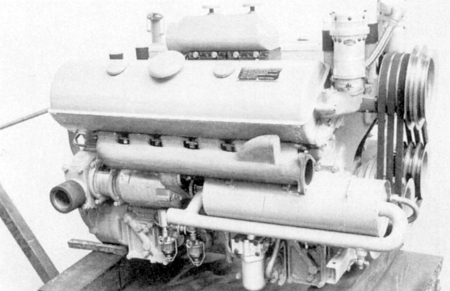
Maybach HL 100 TR used on experimental Begleitwagen tanks.
In November 1936, Krupp was asked to produce a design for a turret armed with a 7.5cm gun, suitable for use on a 30 ton tank.In January 1937, when the tank design office of the ordnance department (Wa Prw 6), asked Henschel to design the chassis for a 30 ton tank.The order was issued to Henschel und Suhn, which chose not to design a new panzer from scratch, but to use ready-made developments. The heaviest German serial tank PzKpfw IV Ausf A was chosen as the initial sample, which had a mass of 17300 kg and had good reserves for modernization.At this stage the new tank was named the Begleitwagen (verstaerkt) or 'escort tank, (strengthened), suggesting that it was seen as having a similar role as the Panzer IV, the original Begleitwagen.
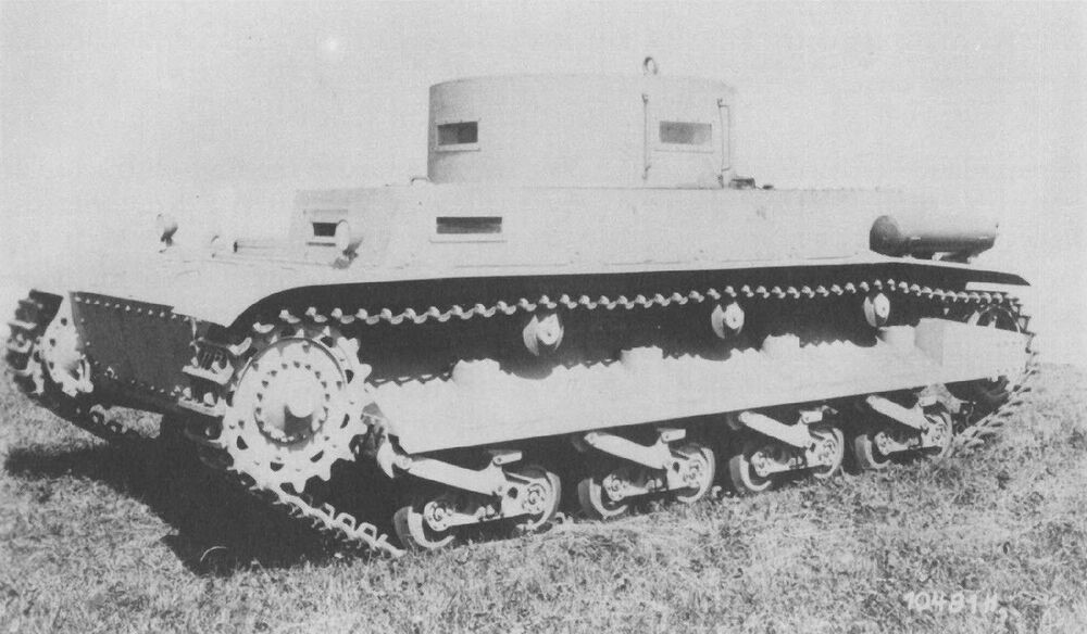
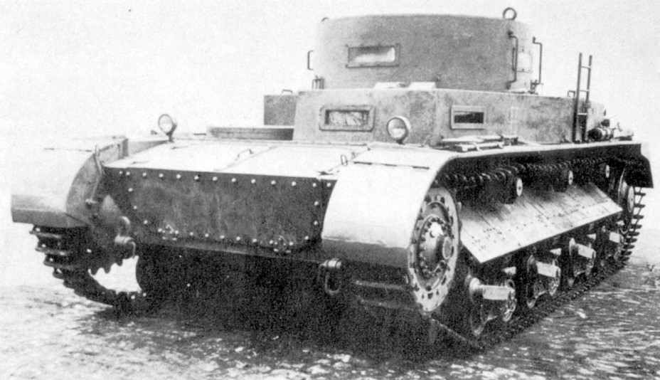
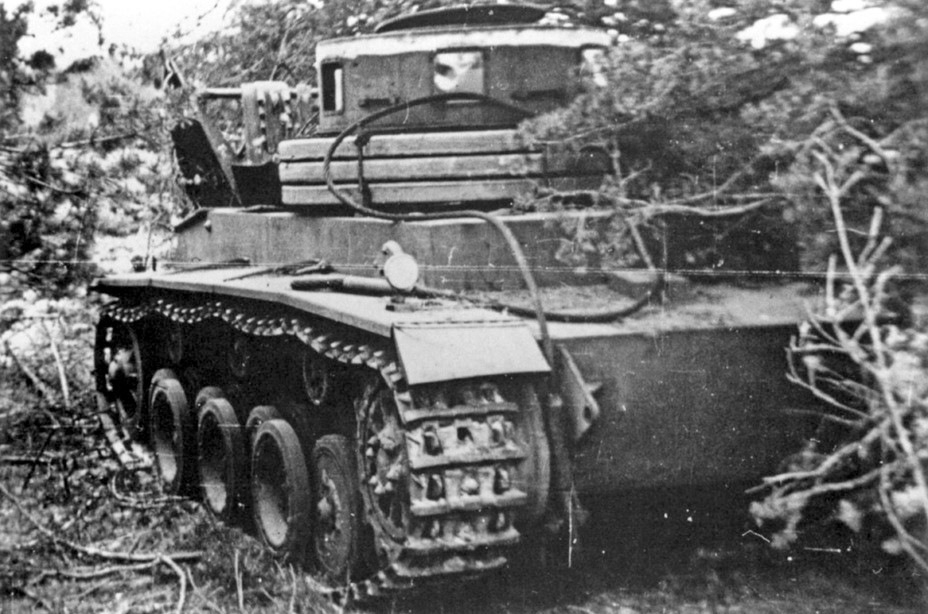
Begleitwagen prototype experimental chassis, summer of 1938. The spaced armour covering the idler and the muffler on the fender are visible
On 12 March 1937 the name was changed to Infanteriewagen, suggesting an infantry support role, but already 27 April 1937 the name was changed once again, this time to Durchbruchswagen (D.W.), or break-through tank.In 1939, after the adoption of the VK designation system, the D.W. became the VK 30.01 alte Konstrucktion (old design), an acknowledgement that was the precursor of the VK 30.01.D.W 1 & 2 had more similar details, a simple boxy hull and superstructure. The superstructure was the same width as the hull, so didn't overlap the tracks. The front of the superstructure was over the front road wheel. The D.W.I had cast steel road wheels with solid rubber double tires, and a 300mm track pitch. It used torsion bar suspension with cushioning to make the ride smoother. It probably had five road wheels on each side, and three return rollers.
Wooden model of the Rheinmetall B.W. This is how the tank was supposed to enter production.
The hull was built in two sections (at this point the available steel mills couldn't produce a long enough piece of rolled steel to allow for a single piece) and bolted together just to the rear of the fighting compartment. A vertical stiffener was added to strengthen the join. The turret ring had a diameter of 1500mm.The sole example was built from soft steel, 50mm thick on the front, sides and rear and 20mm thick on above and below.Steering was provided by Cletrac three stage steering gears arranged in series. Each Cletrac stage contained an idler that slowed down the track it was connected to by a fixed amount, produced a different fixed turning circle.
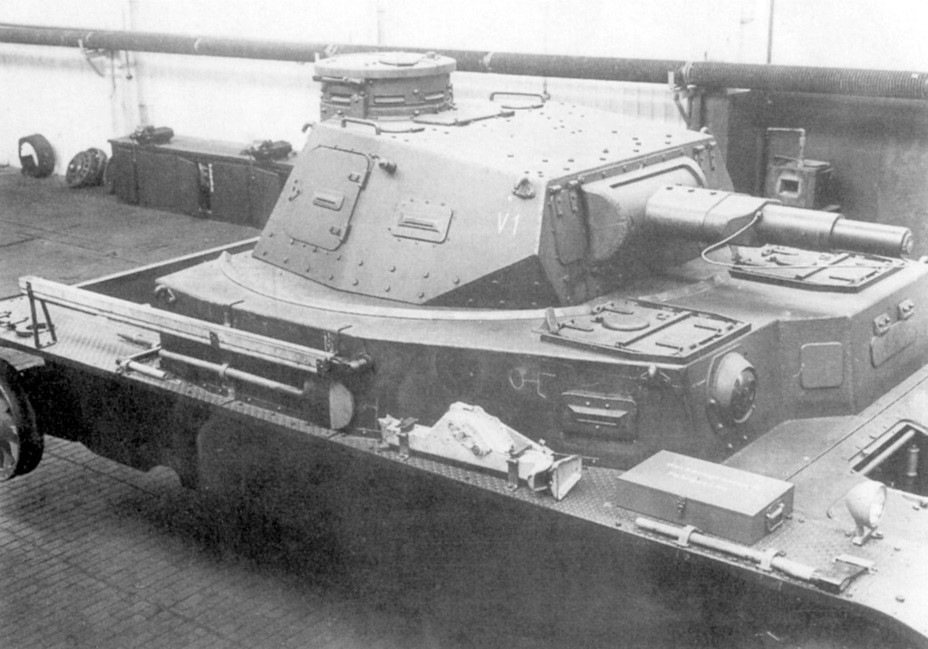
The front of the improved Begleitwagen. The large transmission access hatches are visible. This solution made the transmission easier to service, but was not the greatest for shell resistance.
The D.W.2 have had one piece sides, or they might have been introduced on the VK 30.01 (H). There were five road wheels on each side, constructed from steel, with solid rubber double tire, supported on torsion bars.The D.W.2 used a new steering system. The D.W.1 had used three Cletrac steering gears, arranged in series, on each track. The D.W.2 retained the first Cletrac stage, which produced one fixed turning circle without losing engine power to brakes (using an idler that could be turned on or off to alter the output speed of the transmission).This was connected to a standard three stage differential, presumably with further steering control provided by brakes applied to the tracks, as in simple differential steering systems.The new system rotated in the opposite direction to the system used in the D.W.1, so the final drive, brakes, gear box and even the torsion bars needed to be modified. The final drive was modified, reducing the gear reduction from 1-21.5 to 1 to 12. The torsion bars had the soft springs used on the D.W.1 removed, and were made stronger. The track was reduced in pitch from 300mm to 260mm, and the ride was said to have been much smoother.
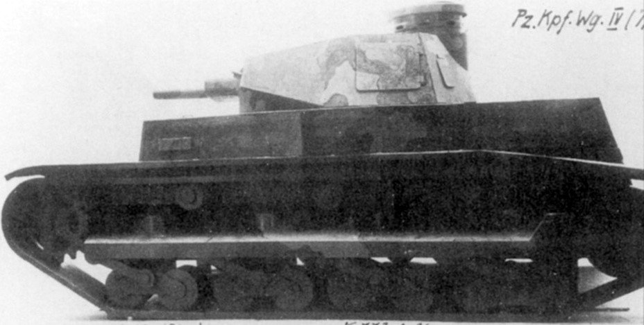
Externally, the first B.W. looks very similar to the PzIV Ausf. A. The similarity is misleading. The tank underwent significant changes, both on the inside and the outside, before it entered production.
The Durchbruchswagens chassis was tested during 1938.9 September 1938 Henschel was ordered to produce an improved 30 ton tank. This new design had three different names. VK 30.01 indicated that it was the first design in the 30 ton tank rank. It was also known as the D.W. neue Knostruktion (new design), and by 31 October 1940 as the Panzerkampfwagen VI (7.5cm).
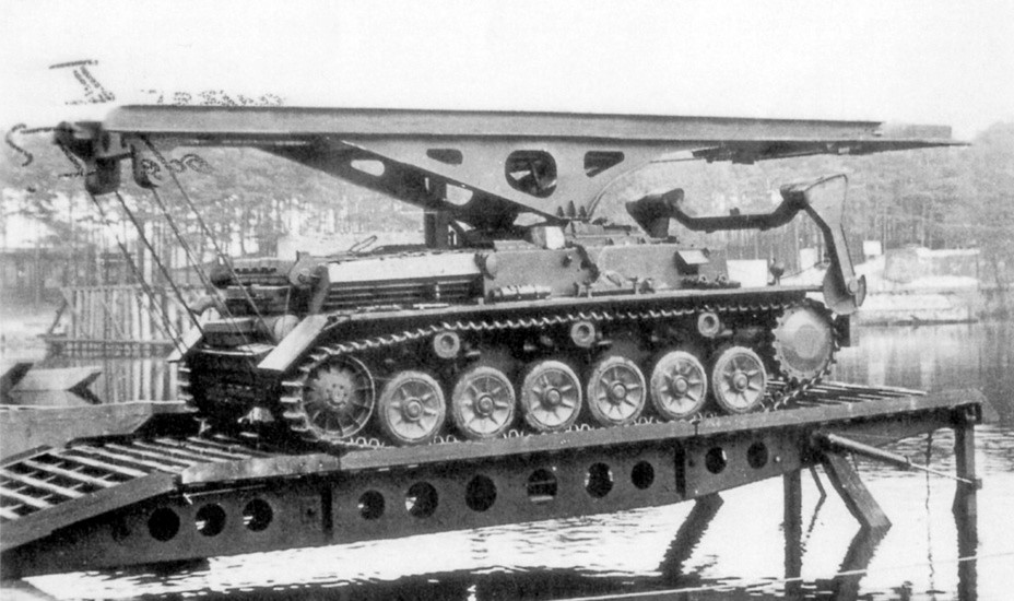
B.W. II Kp converted into a bridgelayer, 1939.
The VK 30.01 (H) was the first to use interleaved road wheels.The basic layout of the tank was similar to the earlier D.W.1 and D.W.2. It had a boxy hull, with a superstructure the same width as the hull (thus not overlapping the top of the tracks). The front of the superstructure was over the front road wheel. The un-lubricated tracks were 520mm wide, and with a pitch of 160mm (shorter than on either of the D.W. models).The VK 30.01 was to be armed with the same 7.5cm Kw.K L/24 gun as used on the Panzer IV, and was to have the same crew space as the lighter tank.The main difference would be in armour, VK 30.01 was to have 50mm front and side armour, which was expected to be effective against uncapped armour piercing shells as fired by the standard German anti tank gun of the time, the 3.7cm PaK L/45.Krupp had the task of producing the turret, just as on the D.W. series. The sides of the D.W. had been made in two pieces, joined just behind the fighting compartment. The VK 30.01 had single piece sides.The VK 30.01 introduced the interleaved road wheels used on the Tiger. There were seven pairs of wheels on each side, with the second, fourth and sixth on the outside and first, third, fifth and seventh on the inside.
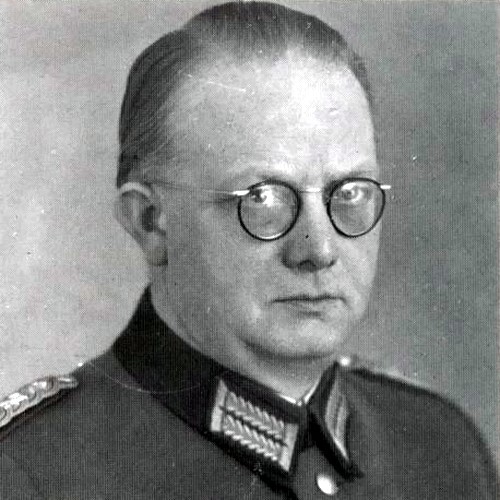
Heinrich Ernst Kniepkamp - the developer of the scheme of staggered placement of rollers on suspensions of German tanks.
This resulted in four rows of narrow wheels (from outside to inside in a three-four-four-three arrangement. This arrangement allowed more road wheels to fit in the same space than a non-overlapped system, and thus helped support the increased weight of the tank.However this system would also prove to be one of the weaknesses of the Tiger, as the narrow gaps between the road wheels could easily get clogged with snow and mud, and freeze solid, while any damage to an inner wheel required all of the rows of outer wheels to be removed and then replaced, a time consuming job. Suspension was provided by simple torsion bars. There were three return rollers, mounted at the top of the hull.
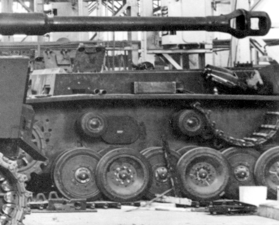
A VK 30.01 made from mild steel, captured at the Sennelager proving grounds near Paderborn in the spring of 1945. The vehicle was being used to test engineering equipment.
The VK 30.01 was powered by a 300hp Maybach HL 116 motor which drove a Maybach-Motorenwerk Variorex gearbox.The VK 30.01 used a new Henschel L.320 C steering gear which used epicyclic double differential steering. This had three steering speeds, and took both its steering drive (to the sun wheels) and main drive (to the annulus) from the output of the main gearbox. It gave the tank three turning radii.This was the precursor of the L.600 C and L.801 transmissions used in the Tiger, but these were more flexible systems, which took the steering drive from the input of the main gears, and the main power from the output, producing sixteen possible turning circles (two steering speeds times eight speeds).
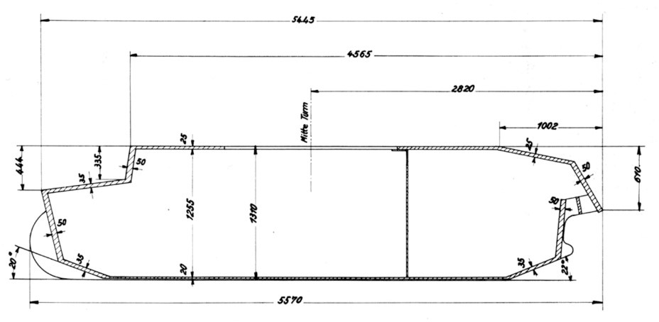
The armour layout of the VK 30.01 as of January 1940. Later, the floor armour was reinforced.
Krupp had produced one example of the D.W. turret, although it was never mounted on either prototype. They then redesigned the turret for the VK 30.01 and the heavier VK 65.01.The two turrets were to be identical apart from side armour thickness - 50mm on the VK 30.01 and 80mm on the VK 65.01. The turret was to carry the 7.5cm gun, a coaxial machine gun, and have a gun port for a second rear-firing machine gun.
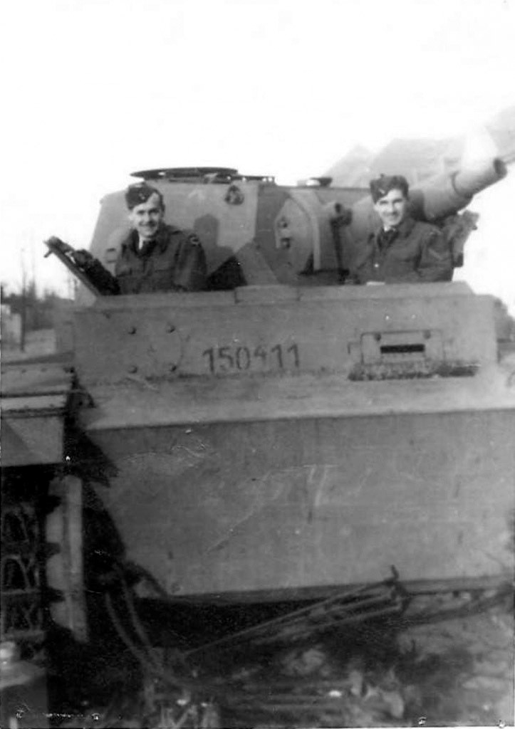
The first tank of the zeroth batch, captured by the British in the spring og 1945. This was the only tank from the D.W./VK 30.01 family to receive a turret.
Towards the end of 1939 Krupp was given an order to build four hulls - one based on the D.W. layout, as the VK 3001 alte Konstrucktion for use in armour penetration tests, and three VK 30.01 neue Konsturktion (new design) hulls with armoured superstructures, for driving trials. By the time the target hull was complete in September 1940 it had been modified to the new standard, and it was used to test the armour against 3.7cm anti-tank gun. The three new design hulls were completed by 1940.
The history of the Tiger tank begins in 1935 from the beginning of the development of a specialized tank engine when Maybach was asked to produce a tank engine, so that the German army could avoid using modified aircraft engines.The aim was to produce 600-700hp engines, but they wouldn't arrive in time for the DW prototypes, which were powered by the 300hp Maybach HL 120 of 1936.
Maybach HL 100 TR used on experimental Begleitwagen tanks.
In November 1936, Krupp was asked to produce a design for a turret armed with a 7.5cm gun, suitable for use on a 30 ton tank.In January 1937, when the tank design office of the ordnance department (Wa Prw 6), asked Henschel to design the chassis for a 30 ton tank.The order was issued to Henschel und Suhn, which chose not to design a new panzer from scratch, but to use ready-made developments. The heaviest German serial tank PzKpfw IV Ausf A was chosen as the initial sample, which had a mass of 17300 kg and had good reserves for modernization.At this stage the new tank was named the Begleitwagen (verstaerkt) or 'escort tank, (strengthened), suggesting that it was seen as having a similar role as the Panzer IV, the original Begleitwagen.
Begleitwagen prototype experimental chassis, summer of 1938. The spaced armour covering the idler and the muffler on the fender are visible
On 12 March 1937 the name was changed to Infanteriewagen, suggesting an infantry support role, but already 27 April 1937 the name was changed once again, this time to Durchbruchswagen (D.W.), or break-through tank.In 1939, after the adoption of the VK designation system, the D.W. became the VK 30.01 alte Konstrucktion (old design), an acknowledgement that was the precursor of the VK 30.01.D.W 1 & 2 had more similar details, a simple boxy hull and superstructure. The superstructure was the same width as the hull, so didn't overlap the tracks. The front of the superstructure was over the front road wheel. The D.W.I had cast steel road wheels with solid rubber double tires, and a 300mm track pitch. It used torsion bar suspension with cushioning to make the ride smoother. It probably had five road wheels on each side, and three return rollers.
Wooden model of the Rheinmetall B.W. This is how the tank was supposed to enter production.
The hull was built in two sections (at this point the available steel mills couldn't produce a long enough piece of rolled steel to allow for a single piece) and bolted together just to the rear of the fighting compartment. A vertical stiffener was added to strengthen the join. The turret ring had a diameter of 1500mm.The sole example was built from soft steel, 50mm thick on the front, sides and rear and 20mm thick on above and below.Steering was provided by Cletrac three stage steering gears arranged in series. Each Cletrac stage contained an idler that slowed down the track it was connected to by a fixed amount, produced a different fixed turning circle.
The front of the improved Begleitwagen. The large transmission access hatches are visible. This solution made the transmission easier to service, but was not the greatest for shell resistance.
The D.W.2 have had one piece sides, or they might have been introduced on the VK 30.01 (H). There were five road wheels on each side, constructed from steel, with solid rubber double tire, supported on torsion bars.The D.W.2 used a new steering system. The D.W.1 had used three Cletrac steering gears, arranged in series, on each track. The D.W.2 retained the first Cletrac stage, which produced one fixed turning circle without losing engine power to brakes (using an idler that could be turned on or off to alter the output speed of the transmission).This was connected to a standard three stage differential, presumably with further steering control provided by brakes applied to the tracks, as in simple differential steering systems.The new system rotated in the opposite direction to the system used in the D.W.1, so the final drive, brakes, gear box and even the torsion bars needed to be modified. The final drive was modified, reducing the gear reduction from 1-21.5 to 1 to 12. The torsion bars had the soft springs used on the D.W.1 removed, and were made stronger. The track was reduced in pitch from 300mm to 260mm, and the ride was said to have been much smoother.
Externally, the first B.W. looks very similar to the PzIV Ausf. A. The similarity is misleading. The tank underwent significant changes, both on the inside and the outside, before it entered production.
The Durchbruchswagens chassis was tested during 1938.9 September 1938 Henschel was ordered to produce an improved 30 ton tank. This new design had three different names. VK 30.01 indicated that it was the first design in the 30 ton tank rank. It was also known as the D.W. neue Knostruktion (new design), and by 31 October 1940 as the Panzerkampfwagen VI (7.5cm).
B.W. II Kp converted into a bridgelayer, 1939.
The VK 30.01 (H) was the first to use interleaved road wheels.The basic layout of the tank was similar to the earlier D.W.1 and D.W.2. It had a boxy hull, with a superstructure the same width as the hull (thus not overlapping the top of the tracks). The front of the superstructure was over the front road wheel. The un-lubricated tracks were 520mm wide, and with a pitch of 160mm (shorter than on either of the D.W. models).The VK 30.01 was to be armed with the same 7.5cm Kw.K L/24 gun as used on the Panzer IV, and was to have the same crew space as the lighter tank.The main difference would be in armour, VK 30.01 was to have 50mm front and side armour, which was expected to be effective against uncapped armour piercing shells as fired by the standard German anti tank gun of the time, the 3.7cm PaK L/45.Krupp had the task of producing the turret, just as on the D.W. series. The sides of the D.W. had been made in two pieces, joined just behind the fighting compartment. The VK 30.01 had single piece sides.The VK 30.01 introduced the interleaved road wheels used on the Tiger. There were seven pairs of wheels on each side, with the second, fourth and sixth on the outside and first, third, fifth and seventh on the inside.
Heinrich Ernst Kniepkamp - the developer of the scheme of staggered placement of rollers on suspensions of German tanks.
This resulted in four rows of narrow wheels (from outside to inside in a three-four-four-three arrangement. This arrangement allowed more road wheels to fit in the same space than a non-overlapped system, and thus helped support the increased weight of the tank.However this system would also prove to be one of the weaknesses of the Tiger, as the narrow gaps between the road wheels could easily get clogged with snow and mud, and freeze solid, while any damage to an inner wheel required all of the rows of outer wheels to be removed and then replaced, a time consuming job. Suspension was provided by simple torsion bars. There were three return rollers, mounted at the top of the hull.
A VK 30.01 made from mild steel, captured at the Sennelager proving grounds near Paderborn in the spring of 1945. The vehicle was being used to test engineering equipment.
The VK 30.01 was powered by a 300hp Maybach HL 116 motor which drove a Maybach-Motorenwerk Variorex gearbox.The VK 30.01 used a new Henschel L.320 C steering gear which used epicyclic double differential steering. This had three steering speeds, and took both its steering drive (to the sun wheels) and main drive (to the annulus) from the output of the main gearbox. It gave the tank three turning radii.This was the precursor of the L.600 C and L.801 transmissions used in the Tiger, but these were more flexible systems, which took the steering drive from the input of the main gears, and the main power from the output, producing sixteen possible turning circles (two steering speeds times eight speeds).
The armour layout of the VK 30.01 as of January 1940. Later, the floor armour was reinforced.
Krupp had produced one example of the D.W. turret, although it was never mounted on either prototype. They then redesigned the turret for the VK 30.01 and the heavier VK 65.01.The two turrets were to be identical apart from side armour thickness - 50mm on the VK 30.01 and 80mm on the VK 65.01. The turret was to carry the 7.5cm gun, a coaxial machine gun, and have a gun port for a second rear-firing machine gun.
The first tank of the zeroth batch, captured by the British in the spring og 1945. This was the only tank from the D.W./VK 30.01 family to receive a turret.
Towards the end of 1939 Krupp was given an order to build four hulls - one based on the D.W. layout, as the VK 3001 alte Konstrucktion for use in armour penetration tests, and three VK 30.01 neue Konsturktion (new design) hulls with armoured superstructures, for driving trials. By the time the target hull was complete in September 1940 it had been modified to the new standard, and it was used to test the armour against 3.7cm anti-tank gun. The three new design hulls were completed by 1940.
Attachments:
Last edit: 1 year 7 months ago by Sasha.
The following user(s) said Thank You: snowman, Juanma66, ShayoX
Please Log in or Create an account to join the conversation.
- Sasha
-
Topic Author
- Offline
- To triumphed over evil, you need only one thing - to good people inaction.
Less
More
- Posts: 497
- Thank you received: 767
1 year 7 months ago #2
by Sasha
Replied by Sasha on topic WW2 Panzer construction history
WW2 Panzer construction history ep.1 - from begleitwagen to 56-ton armored vehicle - story of the Tiger tank (part.2)
In January 1940 Krupp received separate contracts to produce eight armoured hulls (to be delivered between July and October 1941) and eight operational turrets (to be delivered between October 1941 and January 1942). This would give Henschel time to complete work on the hulls and then install the turrets.

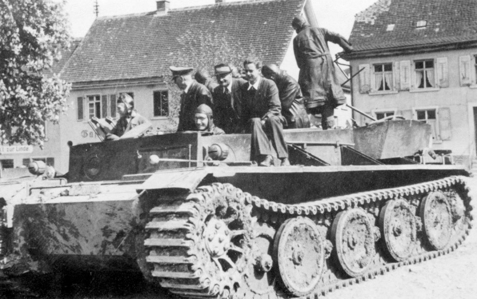
Testing of the bulldozer blade, Henschel proving grounds, January 30th, 1944.
The first hull was delivered to Henschel on 8 August 1941 and the armour for the first two turrets on 27 September 1941. The last hull was sent on 30 November 1941 and the last turret on 21 January 1942.However by this point the number of tanks to be completed urgently had been reduced, from eight to four (two in March 1942 and two in April 1942). The other four weren't cancelled, but construction was suspended. This proved to be a bit optimistic. Henschel delivered two in March and two in October, and the four turrets were completed by September 1942.
VK 30.01 (H) chassis during the process of conversion into a training tank. Henschel factory, April 1942.
By the end of 1941 it was clear that the VK 30.01 would be under-armed. A series of suggestions were made for ways to improve its firepower. In October 1941 Krupp was asked if the longer 7.5cm KwK L/34.5 would fit. Their response was that it would need too many modifications, but the 5cm KwK L./50 or L/60 could be installed. In December Krupp was asked if the 7.5cm KwK 44 l/43 being produced for the Panzer IV could be installed in the eight VK 30.01 turrets, but again the answer was negative. On 30 January 1942 any attempt to up-arm the VK 30.01 was abandoned.Later, two VK 30.01 chassis were converted into 128-mm "Sturer Emil" self-propelled anti-tank guns - they were sent to the Eastern Front and participated in hostilities with the USSR, one of them is preserved in the Kubinka museum in Moscow.

The Pz.Sfl.V at Alkett, March 9th, 1942.
The VK 30.01 was being developed alongside the heavier VK 36.01. Krupp had been working on heavier turrets since the summer of 1939, and Henschel received an order to modify the D.W. chassis to carry the heavier turrets in mid-1940, with the designation D.W. (VK 36.01). They were thus parallel developments for some time, before the larger VK 36.01 became the main priority.Six of the VK 30.01 turrets ended up being used in permanent fortifications. They were armed with the 7.5cm KwK L/24 gun, and a M.G.34 machine gun. They were being modified for use in February 1944, and were ready to be installed by May 1944, and were all installed in either the Atlantic Wall or West Wall.
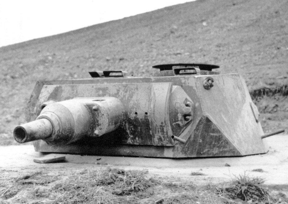
One of six VK 30.01 turrets, converted for use in fortifications Atlantic Wall.
VK 36.01 chassis evolved from earlier chassis has been produced during 1938, followed by three VK 30.01 test chassis in 1940 and eight pre-production VK 30.01 chassis and turrets during 1941.The VK 36.01 retained the boxy structure of the VK 30.01. It was to be powered by a 450 metric HP Maybach HL 174 engine, which drove an eight-speed Maybach Olvar 40 12 16 transmission. Steering was provided by the Henschel L 600 C system, a controlled differential system that would also be used on the Tiger. The VK 36.01 used the same suspension system as the VK 30.01, with pairs of interweaved road wheels carried on torsion bars.
VK 36.01 chassis on trials.
The number of pairs of wheels on each side was increased from seven to eight, with the first wheel on the inside of the track and the second on the outside. The extra set of wheels was introduced to cope with the increase in weight from around 30 tons to 36 tons. After the change of weapon in May 1941 the internal layout had to be modified, and at the same time frontal armour was raised to 100mm and side armour to 60mm. The complete vehicle was now expected to weight 40 tonThe project that led to the VK 36.01 began in June 1939 when Krupp was asked to design a turret to carry a 10.5cm L/20 to L/28 gun, with 100mm armour, to be carried on a Artilleriewagen (A.W.) Panzer. Krupp completed the basic design by 20 October 1939, producing a 2.27m wide turret that needed a 1.75m turret ring, would have weighed 8.4 tons and produced a tank of over 80 tons.
The turret of the VK 36.01 was similar to the VK 30.01(H). Since a larger gun would be installed, the commander and his cupola were shifted to the left.
The campaign of 1940 convinced the Germans that any tank weighting over 30 tons would be of limited use, as they wouldn't be able to cross smaller guns. In June-July 1940 work thus began on a project to produce a turret capable of carrying the 10.5cm gun on the D.W. chassis. In July 1940 Krupp was given the choice of modifying the heavy A.W. turret so it could be carried by the 30 ton D.W., or modifying the existing D.W. turret to carry a 10.5cm gun. The turret was to use a turret ring with a 1.7m diameter, have 80mm frontal armour and 50mm side armour, and be either polygonal or cylindrical.At about the same time Henschel was asked to modify the D.W. chassis to allow it to carry the new turret.Both turret designs continued to be developed for some time.
On 16 September 1940 Krupp was given a contract to produce a 10.5cm L/28 gun to be mounted in a A.W. turret, while on 21 November they were asked to produce a single D.W. test turret, with two mantlets - one made from rolled plate and the other from cast armour.On 18 January 1941 work on the A.W. turret effectively came to an end, when the September contract was modified to cover the D.W. turret instead. In the same month Krupp was asked to produce a complete example of the D.W. turret, with a hydraulic traverse drive.In March 1941 Krupp was asked to send the designs for the D.W. (VK 36.01) (Neukonstruktion) turret to Henschel. In the same month Krupp was informed that they would soon be given a contract to produce four VK 36.01 hulls, to be delivered in January and February 1942. The contract itself was awarded on 5 May 1941, and covered the chassis and turrets.After a conference with Hitler on 26 May 1941 the decision was made to abandon the 10.5cm gun, and instead use a new weapon with high armour penetration - the 75mm Waffe 0725 (or Gerät 725).This was a tapered bore weapon, narrower at the mouth than at the breach. As the shells moved down the barrel they were squeezed and got quicker. The shells had a soft outer section and a hard tungsten core.
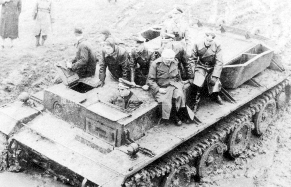
Albert Speer (driver's station) and Ferdinand Porsche (wearing a cap) during trials of the VK 36.01, November 1942.
On 11 June 1941 the original turret contracts were modified. The first order for a single turret was cancelled, and the second one, for four turrets was altered to a contract for six turrets armed with the new Waffe 0725. At the same time Henschel was given a contract to produce one test chassis, which would be used without a turret as a trials vehicle, and six test series vehicles, which would carry the six turrets. Somewhat ironically, at this stage the VK 36.01 was seen as a fore-runner of the rival VK 45.01 (P) Porsche Tiger, which was to be armed with a 88mm gun, also carried in a Krupp turret.In July 1941 it became clear Germany didn't have enough tungsten to waste it in tank shells, and so the VK 36.01 project lost its important.No further vehicles were ordered after the pre-production series of six, and those vehicles were never completed. Henschel did complete the original trials vehicle, the VK 36.01 Fahrgetell, in March 1942.Krupp completed eight armoured hulls, but seven of these were never completed as working tanks. The single completed chassis was used by Maybach for engine tests, and took part in comparison trials in November 1942.
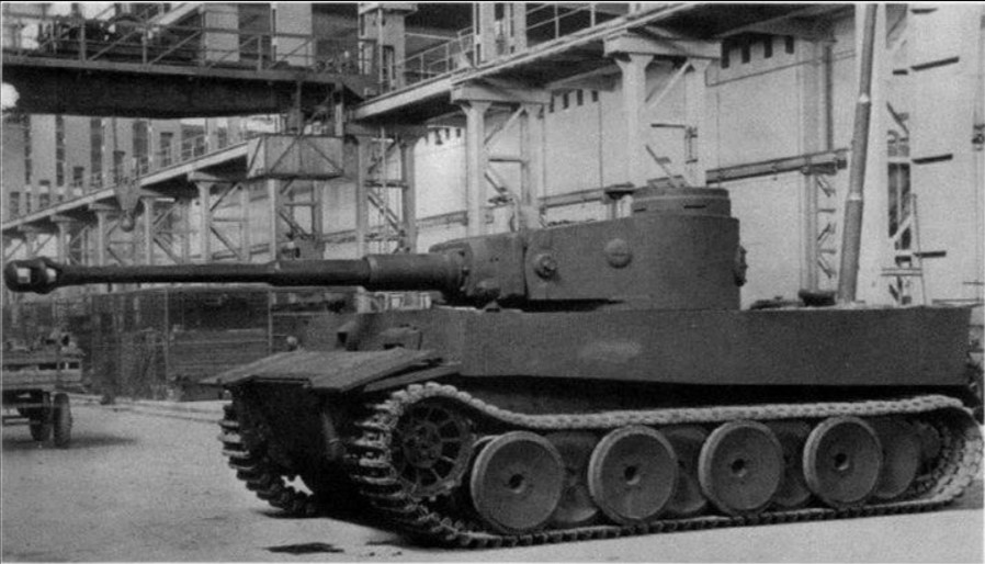
VK 45.01 (H) at the Henschel plant
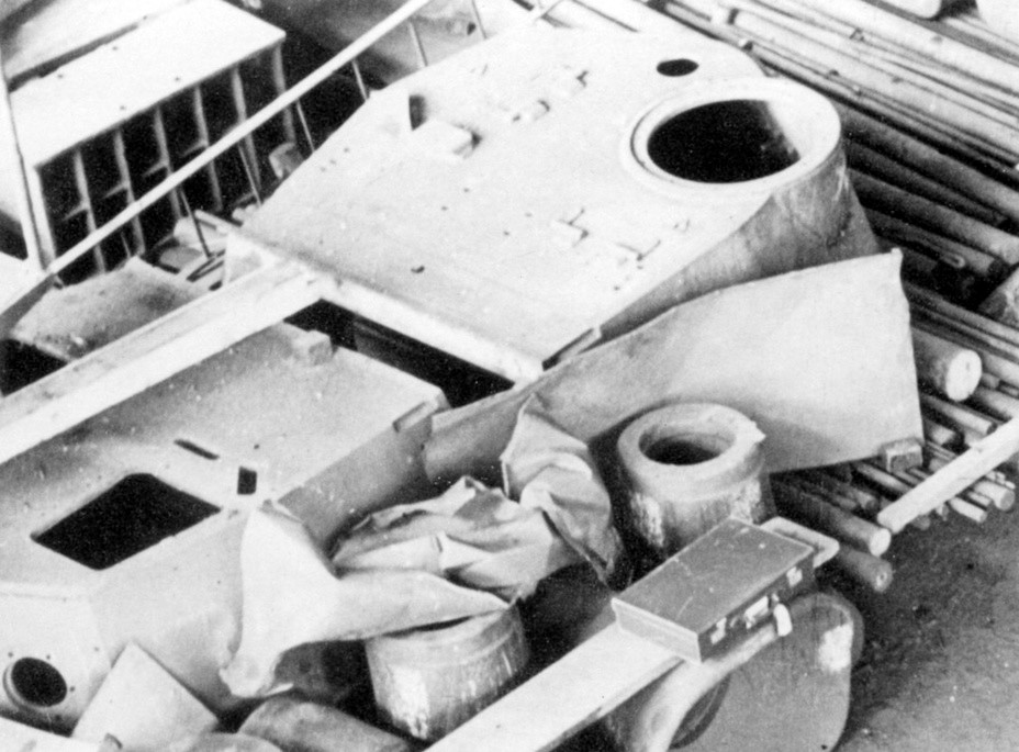
A project did begin to turn five of the VK 36.01s into towing vehicles to be used with the Tiger. The original expectation was that these vehicles would be ready by November 1942, but by September the design had not yet been completed. These vehicles were probably never completed.More progress was made on the turrets. Eight of the production version of the gun, the 7.5cm Kw.K.42, were to be completed between November 1941 and January 1942. The six turrets were to be built between February and April 1942. Work was slow, but the turrets were eventually completed, and turned into turrets for use in fixed defensive positions. The guns were reworked to use stand 75mm ammo designed for the 7.5cm Pak 41 (Krupp). Even now work was slow. None had been installed by March 1945, and five of the six were found incomplete at the Krupp works in Essen after the Allies captured the factory.On 21 October 1941 the new tank was described as the Pz.Kwfw.VI, Ausfuehrung B (VK 36.01).
Henschel's work didn't go to waste. Porsche had been producing its own heavy tank, the VK 45.01 (P), which was armed with a Krupp 88mm anti-tank gun. There had always been a possibility that the Waffe 0725 project wouldn't be practical, and so in May 1941, at the same time as being ordered to modify the VK 36.01 to carry that gun, Henschel were also ordered to redesign the chassis to carry the 8.8cm Kw.K gun. In July 1941, after the decision was made not to use the tapered bore weapons on tanks, Henschel was ordered to modify the design once again, to use the Krupp turret being designed for the VK 45.01 (P).The new design got the designation VK 45.01 (H), and resulting tank began the Panzerkampfwagen Tiger Ausf.E, the famous Tiger I.
In January 1940 Krupp received separate contracts to produce eight armoured hulls (to be delivered between July and October 1941) and eight operational turrets (to be delivered between October 1941 and January 1942). This would give Henschel time to complete work on the hulls and then install the turrets.
Testing of the bulldozer blade, Henschel proving grounds, January 30th, 1944.
The first hull was delivered to Henschel on 8 August 1941 and the armour for the first two turrets on 27 September 1941. The last hull was sent on 30 November 1941 and the last turret on 21 January 1942.However by this point the number of tanks to be completed urgently had been reduced, from eight to four (two in March 1942 and two in April 1942). The other four weren't cancelled, but construction was suspended. This proved to be a bit optimistic. Henschel delivered two in March and two in October, and the four turrets were completed by September 1942.
VK 30.01 (H) chassis during the process of conversion into a training tank. Henschel factory, April 1942.
By the end of 1941 it was clear that the VK 30.01 would be under-armed. A series of suggestions were made for ways to improve its firepower. In October 1941 Krupp was asked if the longer 7.5cm KwK L/34.5 would fit. Their response was that it would need too many modifications, but the 5cm KwK L./50 or L/60 could be installed. In December Krupp was asked if the 7.5cm KwK 44 l/43 being produced for the Panzer IV could be installed in the eight VK 30.01 turrets, but again the answer was negative. On 30 January 1942 any attempt to up-arm the VK 30.01 was abandoned.Later, two VK 30.01 chassis were converted into 128-mm "Sturer Emil" self-propelled anti-tank guns - they were sent to the Eastern Front and participated in hostilities with the USSR, one of them is preserved in the Kubinka museum in Moscow.
The Pz.Sfl.V at Alkett, March 9th, 1942.
The VK 30.01 was being developed alongside the heavier VK 36.01. Krupp had been working on heavier turrets since the summer of 1939, and Henschel received an order to modify the D.W. chassis to carry the heavier turrets in mid-1940, with the designation D.W. (VK 36.01). They were thus parallel developments for some time, before the larger VK 36.01 became the main priority.Six of the VK 30.01 turrets ended up being used in permanent fortifications. They were armed with the 7.5cm KwK L/24 gun, and a M.G.34 machine gun. They were being modified for use in February 1944, and were ready to be installed by May 1944, and were all installed in either the Atlantic Wall or West Wall.
One of six VK 30.01 turrets, converted for use in fortifications Atlantic Wall.
VK 36.01 chassis evolved from earlier chassis has been produced during 1938, followed by three VK 30.01 test chassis in 1940 and eight pre-production VK 30.01 chassis and turrets during 1941.The VK 36.01 retained the boxy structure of the VK 30.01. It was to be powered by a 450 metric HP Maybach HL 174 engine, which drove an eight-speed Maybach Olvar 40 12 16 transmission. Steering was provided by the Henschel L 600 C system, a controlled differential system that would also be used on the Tiger. The VK 36.01 used the same suspension system as the VK 30.01, with pairs of interweaved road wheels carried on torsion bars.
VK 36.01 chassis on trials.
The number of pairs of wheels on each side was increased from seven to eight, with the first wheel on the inside of the track and the second on the outside. The extra set of wheels was introduced to cope with the increase in weight from around 30 tons to 36 tons. After the change of weapon in May 1941 the internal layout had to be modified, and at the same time frontal armour was raised to 100mm and side armour to 60mm. The complete vehicle was now expected to weight 40 tonThe project that led to the VK 36.01 began in June 1939 when Krupp was asked to design a turret to carry a 10.5cm L/20 to L/28 gun, with 100mm armour, to be carried on a Artilleriewagen (A.W.) Panzer. Krupp completed the basic design by 20 October 1939, producing a 2.27m wide turret that needed a 1.75m turret ring, would have weighed 8.4 tons and produced a tank of over 80 tons.
The turret of the VK 36.01 was similar to the VK 30.01(H). Since a larger gun would be installed, the commander and his cupola were shifted to the left.
The campaign of 1940 convinced the Germans that any tank weighting over 30 tons would be of limited use, as they wouldn't be able to cross smaller guns. In June-July 1940 work thus began on a project to produce a turret capable of carrying the 10.5cm gun on the D.W. chassis. In July 1940 Krupp was given the choice of modifying the heavy A.W. turret so it could be carried by the 30 ton D.W., or modifying the existing D.W. turret to carry a 10.5cm gun. The turret was to use a turret ring with a 1.7m diameter, have 80mm frontal armour and 50mm side armour, and be either polygonal or cylindrical.At about the same time Henschel was asked to modify the D.W. chassis to allow it to carry the new turret.Both turret designs continued to be developed for some time.
On 16 September 1940 Krupp was given a contract to produce a 10.5cm L/28 gun to be mounted in a A.W. turret, while on 21 November they were asked to produce a single D.W. test turret, with two mantlets - one made from rolled plate and the other from cast armour.On 18 January 1941 work on the A.W. turret effectively came to an end, when the September contract was modified to cover the D.W. turret instead. In the same month Krupp was asked to produce a complete example of the D.W. turret, with a hydraulic traverse drive.In March 1941 Krupp was asked to send the designs for the D.W. (VK 36.01) (Neukonstruktion) turret to Henschel. In the same month Krupp was informed that they would soon be given a contract to produce four VK 36.01 hulls, to be delivered in January and February 1942. The contract itself was awarded on 5 May 1941, and covered the chassis and turrets.After a conference with Hitler on 26 May 1941 the decision was made to abandon the 10.5cm gun, and instead use a new weapon with high armour penetration - the 75mm Waffe 0725 (or Gerät 725).This was a tapered bore weapon, narrower at the mouth than at the breach. As the shells moved down the barrel they were squeezed and got quicker. The shells had a soft outer section and a hard tungsten core.
Albert Speer (driver's station) and Ferdinand Porsche (wearing a cap) during trials of the VK 36.01, November 1942.
On 11 June 1941 the original turret contracts were modified. The first order for a single turret was cancelled, and the second one, for four turrets was altered to a contract for six turrets armed with the new Waffe 0725. At the same time Henschel was given a contract to produce one test chassis, which would be used without a turret as a trials vehicle, and six test series vehicles, which would carry the six turrets. Somewhat ironically, at this stage the VK 36.01 was seen as a fore-runner of the rival VK 45.01 (P) Porsche Tiger, which was to be armed with a 88mm gun, also carried in a Krupp turret.In July 1941 it became clear Germany didn't have enough tungsten to waste it in tank shells, and so the VK 36.01 project lost its important.No further vehicles were ordered after the pre-production series of six, and those vehicles were never completed. Henschel did complete the original trials vehicle, the VK 36.01 Fahrgetell, in March 1942.Krupp completed eight armoured hulls, but seven of these were never completed as working tanks. The single completed chassis was used by Maybach for engine tests, and took part in comparison trials in November 1942.
VK 45.01 (H) at the Henschel plant
A project did begin to turn five of the VK 36.01s into towing vehicles to be used with the Tiger. The original expectation was that these vehicles would be ready by November 1942, but by September the design had not yet been completed. These vehicles were probably never completed.More progress was made on the turrets. Eight of the production version of the gun, the 7.5cm Kw.K.42, were to be completed between November 1941 and January 1942. The six turrets were to be built between February and April 1942. Work was slow, but the turrets were eventually completed, and turned into turrets for use in fixed defensive positions. The guns were reworked to use stand 75mm ammo designed for the 7.5cm Pak 41 (Krupp). Even now work was slow. None had been installed by March 1945, and five of the six were found incomplete at the Krupp works in Essen after the Allies captured the factory.On 21 October 1941 the new tank was described as the Pz.Kwfw.VI, Ausfuehrung B (VK 36.01).
Henschel's work didn't go to waste. Porsche had been producing its own heavy tank, the VK 45.01 (P), which was armed with a Krupp 88mm anti-tank gun. There had always been a possibility that the Waffe 0725 project wouldn't be practical, and so in May 1941, at the same time as being ordered to modify the VK 36.01 to carry that gun, Henschel were also ordered to redesign the chassis to carry the 8.8cm Kw.K gun. In July 1941, after the decision was made not to use the tapered bore weapons on tanks, Henschel was ordered to modify the design once again, to use the Krupp turret being designed for the VK 45.01 (P).The new design got the designation VK 45.01 (H), and resulting tank began the Panzerkampfwagen Tiger Ausf.E, the famous Tiger I.
Attachments:
The following user(s) said Thank You: snowman, Juanma66, ShayoX
Please Log in or Create an account to join the conversation.
- Sasha
-
Topic Author
- Offline
- To triumphed over evil, you need only one thing - to good people inaction.
Less
More
- Posts: 497
- Thank you received: 767
1 year 7 months ago #3
by Sasha
Replied by Sasha on topic WW2 Panzer construction history
WW2 Panzer construction history ep.1 - from begleitwagen to 56-ton armored vehicle - story of the Tiger tank (part.3)
Porsche's design variants for the Panzer VI Tiger
In September 1939 Ferdinand Porsche was appointed as chairman of the Panzerkommission, giving him a important role in German tank design, and presumably some overview of existing projects.A few months later, in December 1939, Porsche was asked to develop a 25-30 ton heavy tank, which at that point was to be armed with a 7.5cm Kw.K L/24 or possibly a 10.5cm Kw.K.At this stage there were few other limits on the new design, and the sketches show a 8m long, 3m wide tank.During 1940 the tank design bureau of the German Army (Wa Pruef 6) agreed to fund the design and production of trial vehicles, but also gave Porsche some restrictions to operate within (weight, crew, size, armour etc).Porsche concentrated on designing the automotive elements of the new tank, contracting out the detailed work to other companies. Krupp were asked to build the armoured hulls, Steyr to produce the Porsche-designed air-cooled engines, Siemens-Scheuckert to produce the electrics and A.G. the suspension and tracks. The Nibelungenwerk was to assemble to completed tanks.
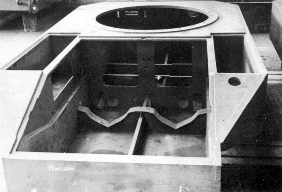
Design of the rear of the second VK 45.01(P) built.
The Porsche design gathered quite an impressive range of names during its development. Porsche called it the Typ 100. Krupp documents refer to it as the VK 30.01 (P) (fully tracked, 30 ton, design 1, Porsche) and the Pz.Kpfw.VI (Porsche). Finally it was also known as the 'Leopard'.The most distinctive feature of the Typ 100 was its petrol-electric drive train. Porsche didn't believe that a normal mechanical transmission could cope with such a heavy tank (it soon grew well above the 30 tons suggested by the VK 30 designation). Instead he preferred a system in which a pair of Porsche 10-cylinder 10 litre engines powered electrical generators, which in turn drove motors that powered the drive wheels. On the Typ 100 the Porsche Typ-100 engines and the generators were at the rear, the motors and drive sprockets at the front.
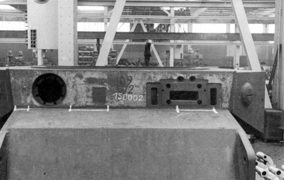
The same hull from the front.
Suspension was provided by six pairs of rubber tired road wheels on each side. These were mounted in pairs. The bogie was attached to the hull by a pivot bearing. A rocker was attached to the pivot. This has a long end and a short end. The long end carried the axle for one of the road wheels. The torsion bar was suspended from this axle, and ran back under the pivot bearing. A rubber block sat between the short end of the rocker and the top of the torsion bar.
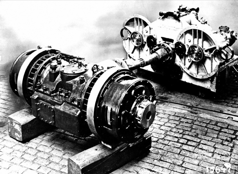
Voith hydromechanical transmission.
The other road wheel was attached to an axle at the end of the torsion bar. Each bogie could thus rock on the pivot, allowing the paired wheels to move, and the torsion bar will have allowed the second road wheel to twist up and down. This torsion bar was mounted quite low down on the road wheels, below the axles, and the system was prone to gather up mud. There were two return rollers.Krupp was given a contract to produce three armoured hulls in March 1941, with deliveries to come seven months after detailed drawings were provided.On 26 May 1941 Hitler held a meeting on tank designs. One of the decisions made at this meeting was to increase the armour on the Porsche tank. This required a sizable increase in weight, and by July further work on the Typ 100 (VK 30.01 P) had been abandoned in favour of the heavier Typ 101 (VK45.01 P), which inherited many features from the earlier design.In July 1941 Krupp's contract was changed to one for the VK 45.01 (P) instead, and no armoured VK 30.01 (P)s were produced. However at least one test chassis was completed. The Eisenwerke Oberdonau of Linz, Austria, was given a contract to produce complete hulls from soft steel, for use in trials. The first of these was accepted in July 1941, in the same month that the first two Porsche Typ 100 engines arrived from Steyr. By the autumn one Typ 100 had been completed, using the soft steel hull, Steyr engines and a circular mock-up of the turret.
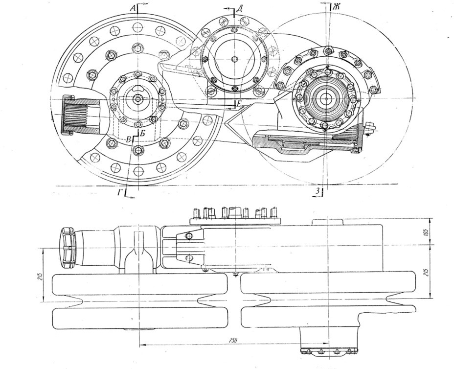
New design of the suspension and road wheels of the Typ 101.
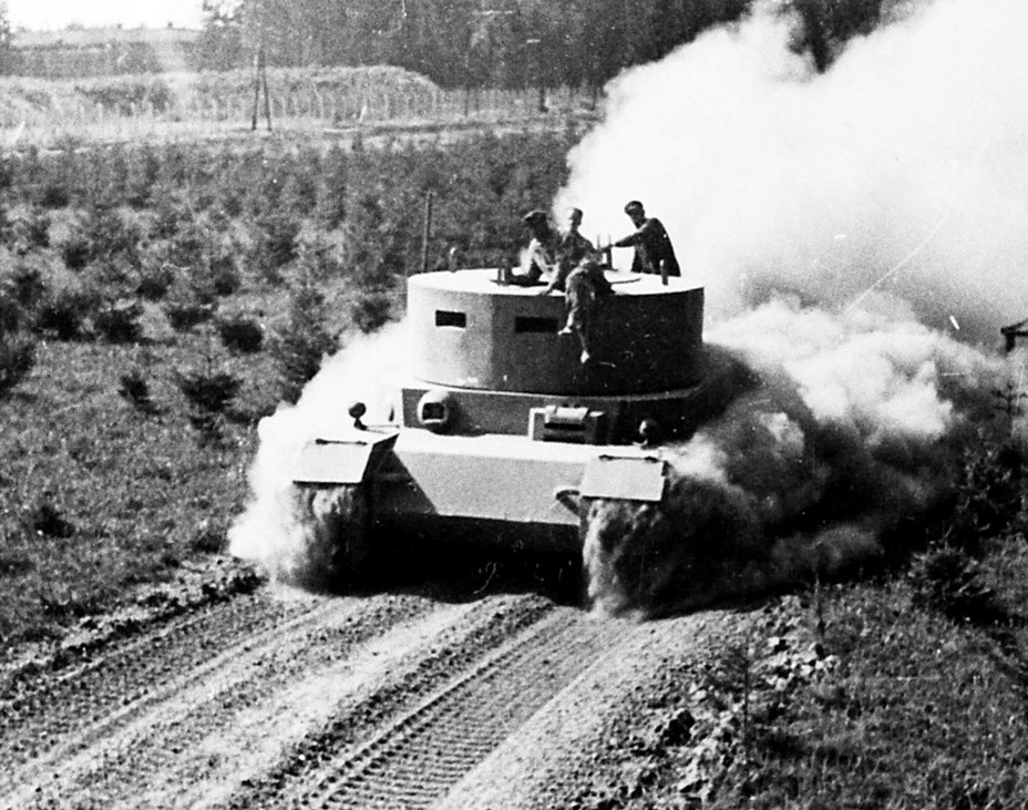
This single tank was used for extensive tests in 1941-42, and after the war Ferdinand Porsche said that it provided valuable experience of electrical steering and for the use of air cooled engines in Panzers.Work on the new design was underway by July at the latest. The Typ 101 or VK 45.01(P) was a slightly enlarged and modified version of the Typ 100. The original 10 litre engines were replaced with an enlarged 15 litre version. The general arrangement drawings went to the engine manufacturer Simmering at the start of September 1941.One major change was that the electric motors and drive sprockets were moved from the front of the tank to the rear, and the turret moved forward to compensate for the extra weight at the rear.In July 1941 Krupp received a contract to provide 100 armoured hulls for the VK 45.01(P) and a separate contract for 100 turrets. These were to delivered to the Nibelungenwerk, where the armour and turret was to added to the chassis to produce complete tanks. The first ten were to be delivered by May 1942.Simmering produced the first Typ 101 engine by December 1941, but this engine failed almost immediately. A second, modified, engine, was ready by 9 March 1942 and performed better in tests. The third engine arrived two days later, giving the two needed for the first tank. These engines went to Nibelungenwerk on 10 April, and were installed in the tank that was displayed in front of Hitler on his birthday a few days later.
The digit 1 marks the first turret.
Tiger (P) production never reached its un-ambitious targets. Krupp began to deliver the armoured hulls in December 1941, and by July 1942 had dispatched 64 (some of these were for the hydraulic powered Typ 102). The first two turrets were completed in April 1942, followed by eight in May, two in July, one in August and one in October, for a total of only 15. Only ten were actually completed at the Nibelungenwerk - the first in April 1942, the second in June, third to sixth in August, seventh to ninth in September and tenth in October. The original target had been to complete 91 by the end of November. In August assembly of the complete tanks was being delayed by the need to make changes to the engine and suspension. In October it was a lack of engine and suspension parts that caused the delay.The Tiger (P) suffered from a number of problems that proved to be very difficult to fix. The Typ 101 engine had a very short lifespan, with performance beginning to fall after only 50 hours. The drive train was also prone to overheating. A second Tiger (P) was sent for tests in June 1942, and this time the engine only lasted 100km.An impressively large number of changes were made to the design of the Tiger (P) in an attempt to fix the problems. These eventually resulted in a change of designation to the Typ 103, which had a redesigned rear deck and twin blowers added to the front of the engines in an attempt to solve the overheating problems.
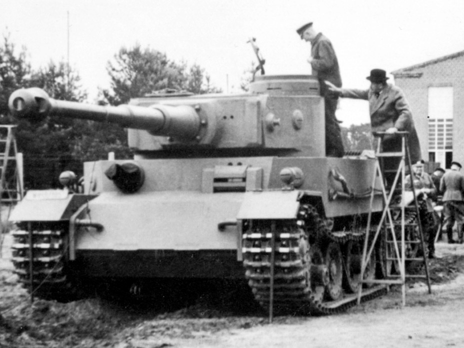
Ferdinand Porsche examines the second mass produced Pz.Kpfw.VI(P1), early June 1942.
On 14 October 1942 Krupp were told to shut down production of the Tiger (P) until further notice. The Tiger (P) took part in driving trials on 8-14 November 1942, and the results can't have been impressive, as on 22 November 1942 production of the Tiger (P) was cancelled. Ninety of the hulls were to be completed as Sturmgeschutz, armed with the long 8.8cm gun.By the time the Tiger (P) was cancelled plans were already in place to deploy forty to North Africa, where the air cooled engines were expected to be an advantage. Both of the units involved were later given the Tiger I.
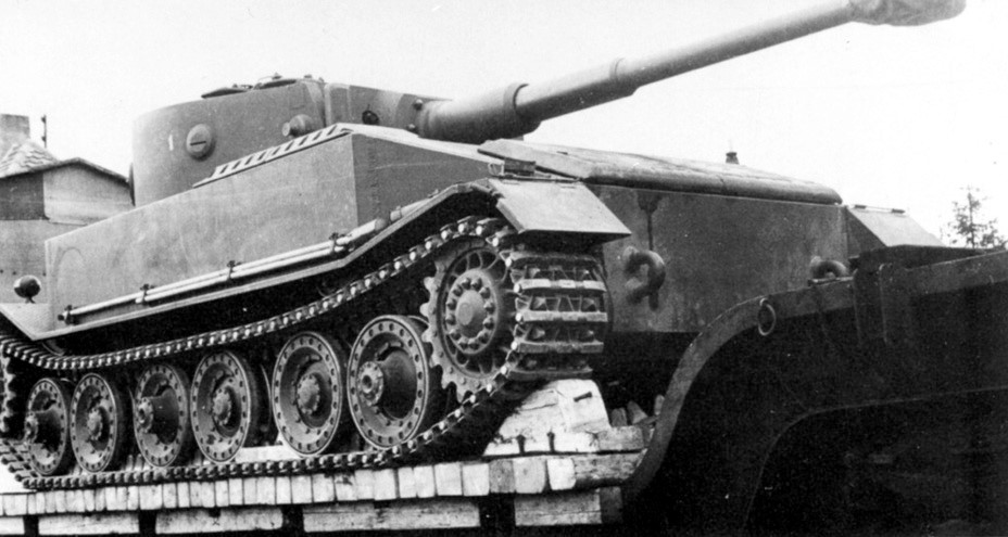
A tank that was used as a test chassis. This is an August-September production vehicle with wide fenders.
Very little went to waste from the Tiger (P) production. Most famously the last ninety of the turrets were installed on ninety of the Tiger I designed by Henschel (the first ten used a slightly different design with a lower roof).Of the 100 hulls, 91 were completed as the Panzerjäger 'Tiger P' Ferdinand, which carried a longer 88mm gun.
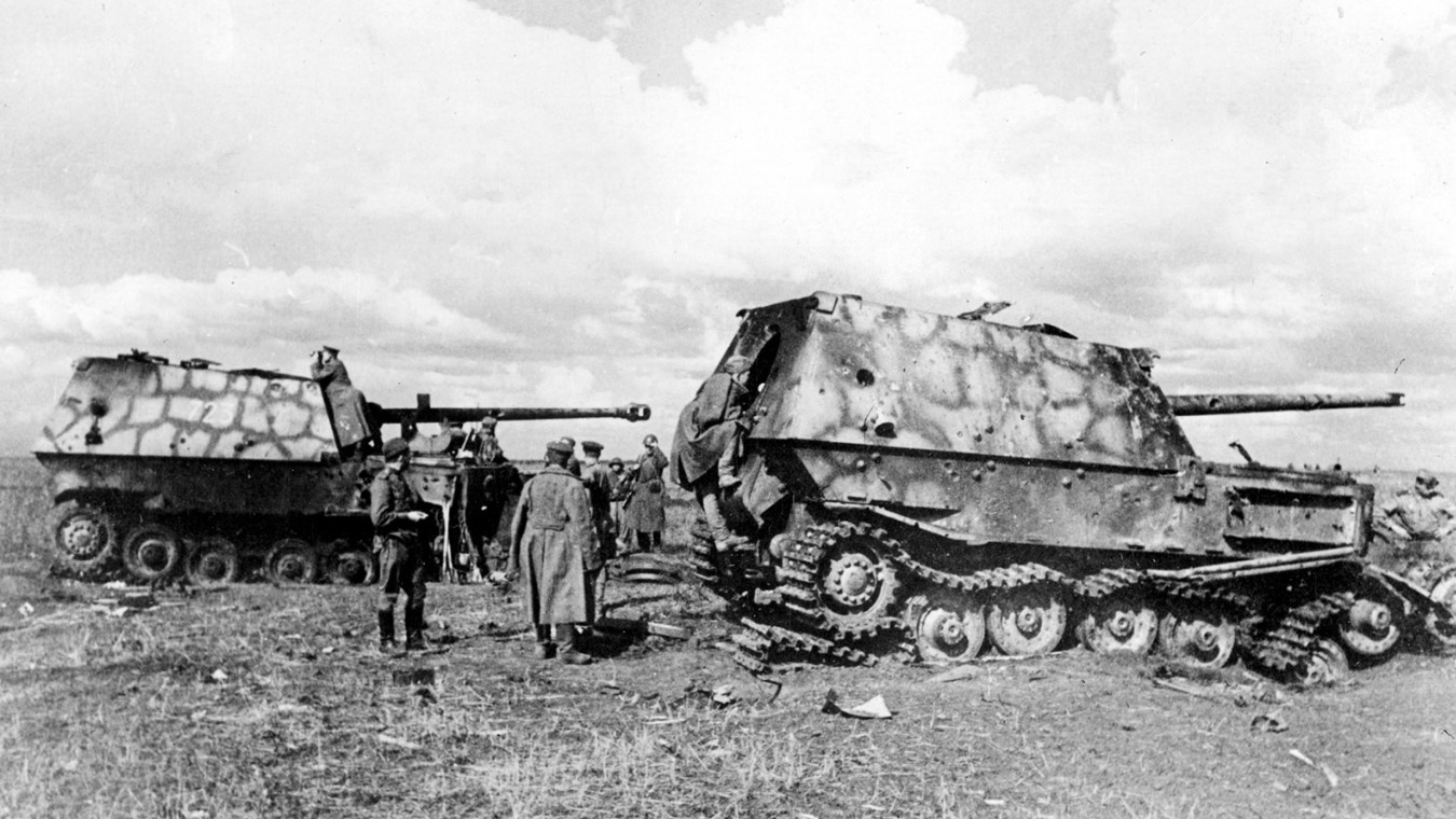
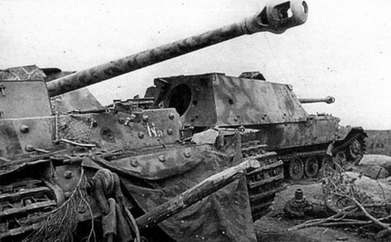
Destroyed Ferdinand's from sPzJgAbt 654 summer 1943, Operation Citadel
Three were completed as recovery vehicles - the Bergepanzer VI or Bergepanzer Tiger (P).Three were used as the basis of the Ramm-Tiger, an odd idea for a vehicle capable of destroying buildings by ramming them. Just how much progress was made on this scheme is unclear.
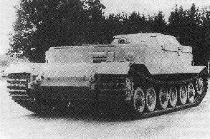
Bergepanzer Tiger (P)
One was completed as a Typ 102, using a hydraulic drive train.Two were completed as Tiger (P)s. Of these one was converted into a command tank. It was used for a series of trials before early in 1944 it was given Maybach engines and then sent to the Eastern Front, where it served with schwere Heeres Panzer-Jäger-Abteilung 653. The tank entered combat in April and was lost in combat in July 1944, making it the only Tiger (P) to actually see combat as a tank.
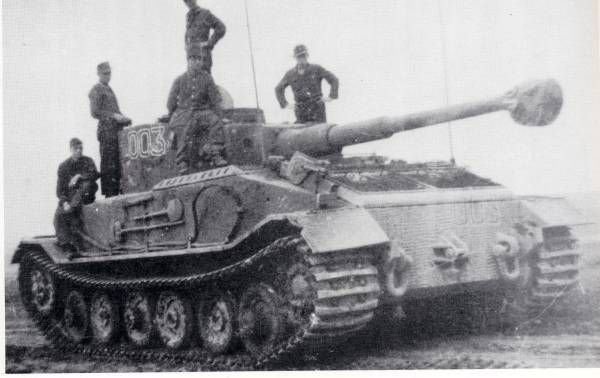
The only Porsche Tiger to enter service as a command tank in Schwere Panzerjäger Abteilung 653
Materials used in the creation of the article - link
Porsche's design variants for the Panzer VI Tiger
In September 1939 Ferdinand Porsche was appointed as chairman of the Panzerkommission, giving him a important role in German tank design, and presumably some overview of existing projects.A few months later, in December 1939, Porsche was asked to develop a 25-30 ton heavy tank, which at that point was to be armed with a 7.5cm Kw.K L/24 or possibly a 10.5cm Kw.K.At this stage there were few other limits on the new design, and the sketches show a 8m long, 3m wide tank.During 1940 the tank design bureau of the German Army (Wa Pruef 6) agreed to fund the design and production of trial vehicles, but also gave Porsche some restrictions to operate within (weight, crew, size, armour etc).Porsche concentrated on designing the automotive elements of the new tank, contracting out the detailed work to other companies. Krupp were asked to build the armoured hulls, Steyr to produce the Porsche-designed air-cooled engines, Siemens-Scheuckert to produce the electrics and A.G. the suspension and tracks. The Nibelungenwerk was to assemble to completed tanks.
Design of the rear of the second VK 45.01(P) built.
The Porsche design gathered quite an impressive range of names during its development. Porsche called it the Typ 100. Krupp documents refer to it as the VK 30.01 (P) (fully tracked, 30 ton, design 1, Porsche) and the Pz.Kpfw.VI (Porsche). Finally it was also known as the 'Leopard'.The most distinctive feature of the Typ 100 was its petrol-electric drive train. Porsche didn't believe that a normal mechanical transmission could cope with such a heavy tank (it soon grew well above the 30 tons suggested by the VK 30 designation). Instead he preferred a system in which a pair of Porsche 10-cylinder 10 litre engines powered electrical generators, which in turn drove motors that powered the drive wheels. On the Typ 100 the Porsche Typ-100 engines and the generators were at the rear, the motors and drive sprockets at the front.
The same hull from the front.
Suspension was provided by six pairs of rubber tired road wheels on each side. These were mounted in pairs. The bogie was attached to the hull by a pivot bearing. A rocker was attached to the pivot. This has a long end and a short end. The long end carried the axle for one of the road wheels. The torsion bar was suspended from this axle, and ran back under the pivot bearing. A rubber block sat between the short end of the rocker and the top of the torsion bar.
Voith hydromechanical transmission.
The other road wheel was attached to an axle at the end of the torsion bar. Each bogie could thus rock on the pivot, allowing the paired wheels to move, and the torsion bar will have allowed the second road wheel to twist up and down. This torsion bar was mounted quite low down on the road wheels, below the axles, and the system was prone to gather up mud. There were two return rollers.Krupp was given a contract to produce three armoured hulls in March 1941, with deliveries to come seven months after detailed drawings were provided.On 26 May 1941 Hitler held a meeting on tank designs. One of the decisions made at this meeting was to increase the armour on the Porsche tank. This required a sizable increase in weight, and by July further work on the Typ 100 (VK 30.01 P) had been abandoned in favour of the heavier Typ 101 (VK45.01 P), which inherited many features from the earlier design.In July 1941 Krupp's contract was changed to one for the VK 45.01 (P) instead, and no armoured VK 30.01 (P)s were produced. However at least one test chassis was completed. The Eisenwerke Oberdonau of Linz, Austria, was given a contract to produce complete hulls from soft steel, for use in trials. The first of these was accepted in July 1941, in the same month that the first two Porsche Typ 100 engines arrived from Steyr. By the autumn one Typ 100 had been completed, using the soft steel hull, Steyr engines and a circular mock-up of the turret.
New design of the suspension and road wheels of the Typ 101.
This single tank was used for extensive tests in 1941-42, and after the war Ferdinand Porsche said that it provided valuable experience of electrical steering and for the use of air cooled engines in Panzers.Work on the new design was underway by July at the latest. The Typ 101 or VK 45.01(P) was a slightly enlarged and modified version of the Typ 100. The original 10 litre engines were replaced with an enlarged 15 litre version. The general arrangement drawings went to the engine manufacturer Simmering at the start of September 1941.One major change was that the electric motors and drive sprockets were moved from the front of the tank to the rear, and the turret moved forward to compensate for the extra weight at the rear.In July 1941 Krupp received a contract to provide 100 armoured hulls for the VK 45.01(P) and a separate contract for 100 turrets. These were to delivered to the Nibelungenwerk, where the armour and turret was to added to the chassis to produce complete tanks. The first ten were to be delivered by May 1942.Simmering produced the first Typ 101 engine by December 1941, but this engine failed almost immediately. A second, modified, engine, was ready by 9 March 1942 and performed better in tests. The third engine arrived two days later, giving the two needed for the first tank. These engines went to Nibelungenwerk on 10 April, and were installed in the tank that was displayed in front of Hitler on his birthday a few days later.
The digit 1 marks the first turret.
Tiger (P) production never reached its un-ambitious targets. Krupp began to deliver the armoured hulls in December 1941, and by July 1942 had dispatched 64 (some of these were for the hydraulic powered Typ 102). The first two turrets were completed in April 1942, followed by eight in May, two in July, one in August and one in October, for a total of only 15. Only ten were actually completed at the Nibelungenwerk - the first in April 1942, the second in June, third to sixth in August, seventh to ninth in September and tenth in October. The original target had been to complete 91 by the end of November. In August assembly of the complete tanks was being delayed by the need to make changes to the engine and suspension. In October it was a lack of engine and suspension parts that caused the delay.The Tiger (P) suffered from a number of problems that proved to be very difficult to fix. The Typ 101 engine had a very short lifespan, with performance beginning to fall after only 50 hours. The drive train was also prone to overheating. A second Tiger (P) was sent for tests in June 1942, and this time the engine only lasted 100km.An impressively large number of changes were made to the design of the Tiger (P) in an attempt to fix the problems. These eventually resulted in a change of designation to the Typ 103, which had a redesigned rear deck and twin blowers added to the front of the engines in an attempt to solve the overheating problems.
Ferdinand Porsche examines the second mass produced Pz.Kpfw.VI(P1), early June 1942.
On 14 October 1942 Krupp were told to shut down production of the Tiger (P) until further notice. The Tiger (P) took part in driving trials on 8-14 November 1942, and the results can't have been impressive, as on 22 November 1942 production of the Tiger (P) was cancelled. Ninety of the hulls were to be completed as Sturmgeschutz, armed with the long 8.8cm gun.By the time the Tiger (P) was cancelled plans were already in place to deploy forty to North Africa, where the air cooled engines were expected to be an advantage. Both of the units involved were later given the Tiger I.
A tank that was used as a test chassis. This is an August-September production vehicle with wide fenders.
Very little went to waste from the Tiger (P) production. Most famously the last ninety of the turrets were installed on ninety of the Tiger I designed by Henschel (the first ten used a slightly different design with a lower roof).Of the 100 hulls, 91 were completed as the Panzerjäger 'Tiger P' Ferdinand, which carried a longer 88mm gun.
Destroyed Ferdinand's from sPzJgAbt 654 summer 1943, Operation Citadel
Three were completed as recovery vehicles - the Bergepanzer VI or Bergepanzer Tiger (P).Three were used as the basis of the Ramm-Tiger, an odd idea for a vehicle capable of destroying buildings by ramming them. Just how much progress was made on this scheme is unclear.
Bergepanzer Tiger (P)
One was completed as a Typ 102, using a hydraulic drive train.Two were completed as Tiger (P)s. Of these one was converted into a command tank. It was used for a series of trials before early in 1944 it was given Maybach engines and then sent to the Eastern Front, where it served with schwere Heeres Panzer-Jäger-Abteilung 653. The tank entered combat in April and was lost in combat in July 1944, making it the only Tiger (P) to actually see combat as a tank.
The only Porsche Tiger to enter service as a command tank in Schwere Panzerjäger Abteilung 653
Materials used in the creation of the article - link
Attachments:
The following user(s) said Thank You: snowman, Juanma66, Stern, ShayoX
Please Log in or Create an account to join the conversation.
- spartacus birthday is in 4 days (63)
- Kahuna birthday is in 5 days (39)
- Wójt birthday is in 9 days (28)